02 Data Center & Colocation Solutions
Capacity sized to your density.
High-density AI hardware needs more than floor space. We help you define what you need, evaluate facilities against evidence, and get your equipment installed in space that can actually power and cool it.
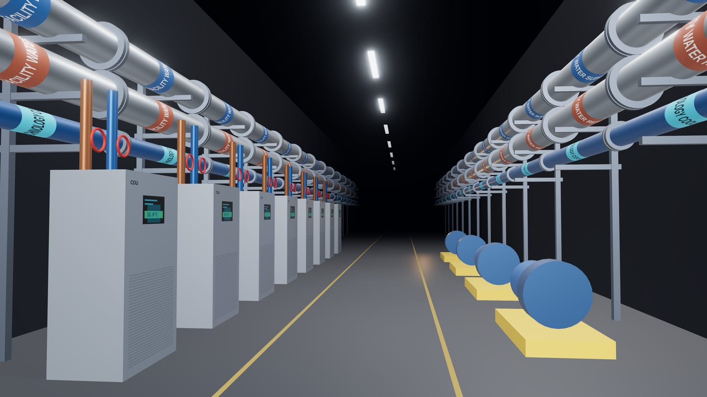
Illustrative 3D rendering — facility-water gallery with coolant distribution units.
What we deliver
From requirement to racks energised.
Colocation for AI is decided by power density, cooling and timing. We make those requirements explicit, then hold every option to them.
- Requirements
Capacity definition
Critical IT load, rack density, redundancy, growth path and timeline, written down as a specification you can take to market.
- Due diligence
Facility evaluation
Available power, cooling capability and delivery dates checked against evidence — not brochure figures.
- Liquid cooling
High-density readiness
Direct-to-chip and rear-door cooling requirements, facility water and floor loading confirmed before contract.
- Network
Connectivity planning
Carrier diversity, cross-connects and on-ramps sized for training data movement and inference traffic.
- Move-in
Deployment & migration
Installation sequencing, power-on testing and migration plans that protect live services.
- Growth
Ongoing capacity planning
Utilisation tracking and expansion options reviewed before you run out of headroom.
Capacity scenario
Model your deployment.
Change the load, the density and the efficiency target to see racks, facility power, annual energy and the cooling approach the design calls for. No sign-up required.
Cooling approach vs. rack density
│ your scenario: 130 kW/rackIndicative industry ranges; achievable density depends on supply temperatures, containment quality and the specific equipment. Cognivox does not publish facility availability; capacity is evaluated per requirement.
Start a conversation
Tell us what you are planning.
Load, timeline, location, constraints — whatever you know so far. An engineer will reply.